
Civil 3D and Obi Obi Road – Longsections (Profile)

Image Capture, Google Maps 2020.
I am currently revisiting the concept of longitudinal sections (profiles) that I studied during my time at college. I recall working on these sections with great interest, whether they were used for pipe designs for stormwater management or road designs. Additionally, I had experience using Civil 3D software back in 2022.
I recently downloaded Civil 3D to reacquaint myself with long sections (profiles), contours, and road design. This document outlines my experiences thus far.
Civil 3D differs significantly from AutoCAD, particularly in terms of tools and application commands. To import contours, I utilized the open-source GIS software program QGIS. Although I will not delve into the specifics of obtaining contours from QGIS, I successfully acquired raster images from Elvis Lidar, imported them into QGIS, converted them to contours, and exported them as a DXF file.
…Which cannot be opened in the Civil 3D template, but can be accessed in AutoCAD. To import the contours into Civil 3D, I performed a `copybase` operation at coordinates (0,0,0) and subsequently pasted it at the same coordinates in a Civil 3D template.
The contours are from an area between Mapleton and Kenilworth, showing Obi Obi road. I wanted to view this road in long section and see if there were alternative ways down from Mapleton to Kenilworth. The alternative ways will be three profiles that I have selected to view the grade of the existing surface.

Obi Obi Road, and three profiles shown in a contour map in QGIS. 2025 Google Maps and Google Earth.
Obi Obi Road extends towards Kenilworth from Mapleton. There is a section approximately 2 kilometres long on this road that is both narrow and steep.
Traveling from Mapleton to Kenilworth can be done either by going north via Eerwah Vale, which takes approximately 50 minutes for 60 kilometres, or by going south via Maleny, which takes about an hour for 64 kilometres. The direct route via Obi Obi Road is 21.5 kilometres and takes about 23 minutes. This includes the 2 kilometre section I will analyse..

Mapleton to Kenilworth via Eerwah Vale, distance and time. 2025 Google Maps.

Mapleton to Kenilworth via Maleny. 2025 Google Maps.

Mapleton to Kenilworth, Obi Obi Road. 2025 Google Maps.
Having traversed this road in a Hyundai i30, I would advise against using it again due to its challenging conditions. Despite its difficulties, The scenery on this road is spectacular and is possibly the last thing that you see as you are going over the edge. It may be beneficial to consider renaming this road to Agrippa Road, cause Agrippa is what you are doing with the steering wheel. This section of road is one way only.
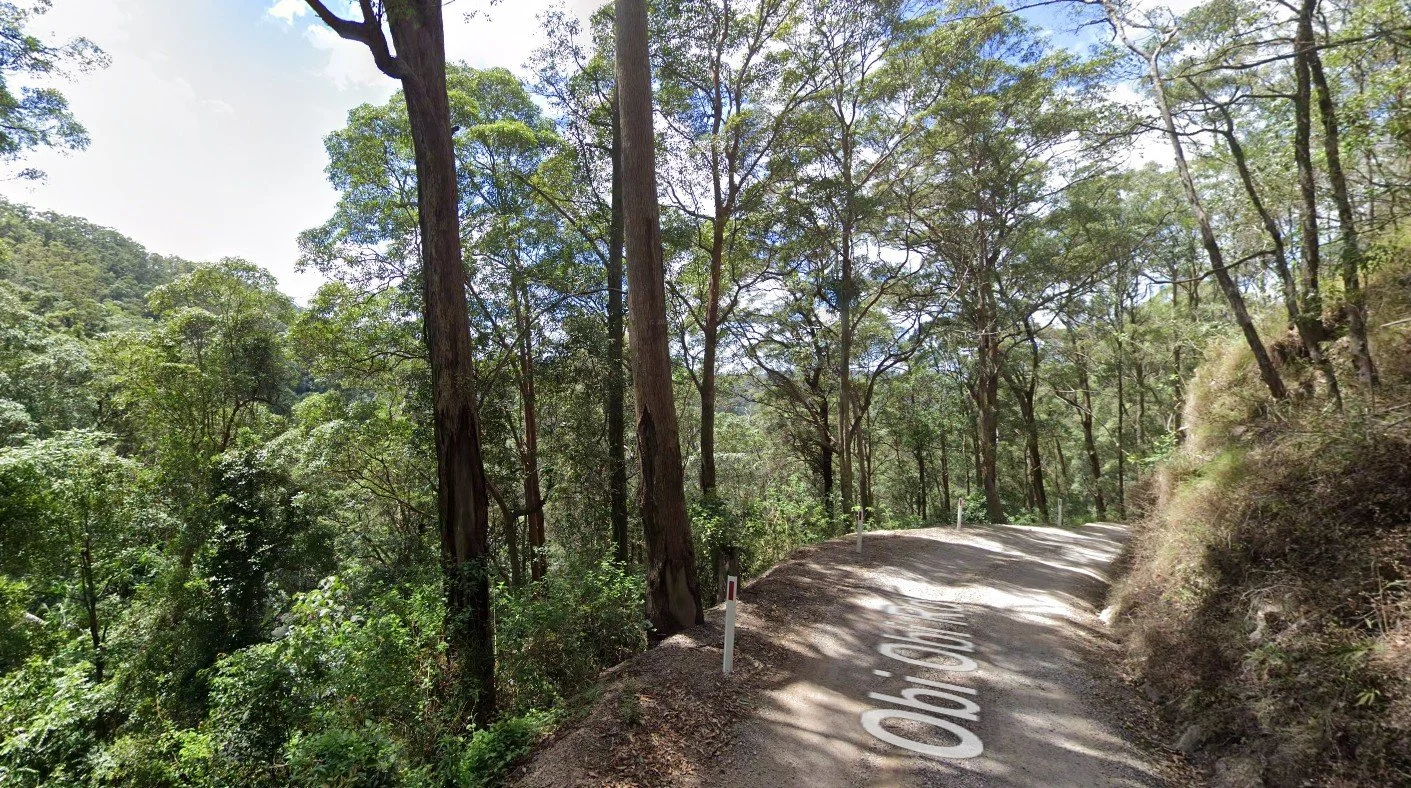
Obi Obi Road 2020 Google Maps.
So here is this road, in contour with the longsection (profile) in Civil 3D. Please feel free to play the video.
This section of road is approximately 2.05 kilometres long and features an approximate grade at the top of 2% and 12% at the bottom.

Road and Profile Longsection. Esri OpenStreet map Google 2025.
I have explored potential alternative routes for road construction. To clarify, there are no plans to design or build roads in this area. The proposed profiles, I have identified, are through private property and the grading of these routes is significantly more challenging than that of Obi Obi Road. This Stretch of Obi Obi Road and all proposed profiles are shown in red in the following map. George Wyer Scenic Drive is one way heading up towards Mapleton.

Showing Obi Obi Rd and profiles in relation to Obi Obi Rd. Esri OpenStreet Map Google 2025.

Esri Imagery Map Google 2025.
My 1st Profile is located between the 2 kilometre problematic stretch of Obi Obi Road and Mapleton. This alignment begins at the top of Obi Obi Road and follows a ridge line towards Pencil Creek Road. It then diverges towards Falls Creek Road, as Falls Creek Road features a bridge over Pencil Creek.
The profile is approximately 2.25 kilometres with the grade being approximately 59% at the top and 10% at the bottom.
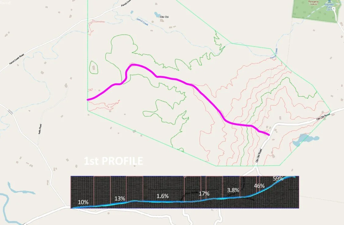
1st Profile and Profile Longsection. Esri OpenStreet Map Google 2025.
The 2nd Profile is just North of Mapleton and goes through a national park. The profile is approximately 1.56 kilometres with the grade from top at approximately 45% and 10% at the bottom.

2nd Profile and Profile Longsection. Esri OpenStreet Map Google 2025.
The 3rd Profile is North of Mapleton off Delicia Road and heading down to Pencil Creek road. This profile is approximately 1.22 kilometres long and has an approximate grade of 19% at the top and 8% at the bottom.

3rd Profile and Profile Longsection. Esri OpenStreet Map Google 2025.
It seems like there is no other way to get off this mountain range other than Obi Obi road or possibly via Delicia road, with an upgrade and less than direct path to Kenilworth. But that is something that I would have to explore further. I have explored other profiles to try and reduced the grade but it still seems the same and really I could play with this all night. On another note, I don’t have any geotechnical for the area, and there are waterfalls that come off this range. So, rocks. Sheer, steep rocks.
Maybe I could investigate this further. I will see what happens or where I go with this. Meanwhile here is another picture of Obi Obi Road and the three profiles I picked.
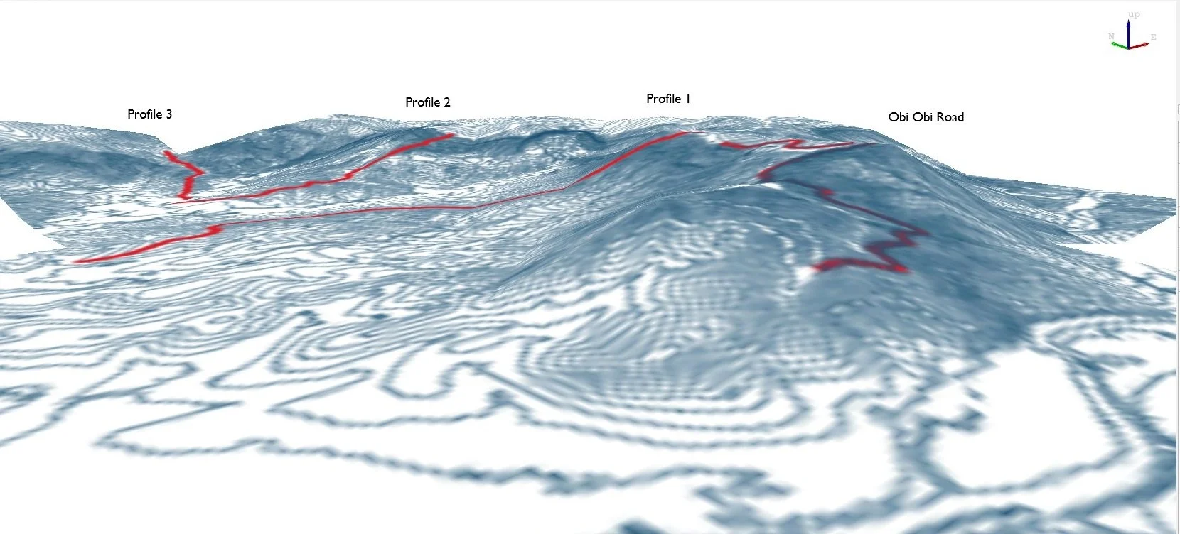
Contours from QGIS, Extracted from raster images from Elvis Lidar.

I reviewed AutoCAD fonts against Australian Standard AS 1100.101-1992. Here are the results
It all begins with an idea.
I am developing a template in AutoCAD that adheres to the Australian Standards AS 1100.101-1992 Technical Drawing Part 101 General Principles.
In this article, I am focusing on the section concerning LETTERINGS and NUMERALS also known as FONTS.
To evaluate which font to use in my template, I will be doing a comparison of various fonts against the Australian Standards AS 1100.101-1992. I will be creating a font table listing each font's compliance with the Standards. Additionally, in AutoCAD, I will be presenting fonts with the sentence, "The quick brown fox jumped over the lazy dogs," in both upper case and lower case, along with numerals and symbols. This information will be plotted onto an A1 sheet. Both shx and True Type fonts will be included.
The height of the characters are 5mm.
The maximum line thickness of the characters to be 0.1 times the height (h), where h is defined as 5 mm. Hence 0.5mm
The spacing between characters to be twice the thickness of character lines or at least 1mm, whichever is greater.
Word spacing to be between 0.6h and 2h. 3mm and 10mm
Spacing between lines to be 0.6h
The Australian Standard specifies the use of these fonts:
Upright Gothic, Sloping Gothic
ISO 3098/1 Type B Upright, ISO 3098/1 Type B Sloping
Microfont
I didn't include examples of ISOCT fonts as the sentence length was 250mm with a character height of 5mm on A1. I have limited the sentence length to 230mm.

Spreadsheet tracking fonts in comparison to the Australian Standards
ISO 3098/1 Type B characters are not specified as a particular font in the AutoCAD software. It is unclear whether this font style can be sourced and imported into AutoCAD, or if it simply defines the appearance of the chosen font. There are Reddit posts and blogs that do provide links to an "ISO3098B.SHX" file for download; I have not clicked on these links. Regarding ISO 3098 characters, it is presumed that the ISO and ISOCP fonts in AutoCAD reflect the ISO 3098 characters.
The difference between the ISOCP font and the ISOCT font has been noted in a group chat from 1995, which states, "ISOCP is the Proportional font. ISOCT is the tabular or fixed-width font." Thanks to K.C. Jones on groups. google. com, comp. cad. autocad (and no I am not stringing these together). But other than that, I have been unable to find any information that verifies this.
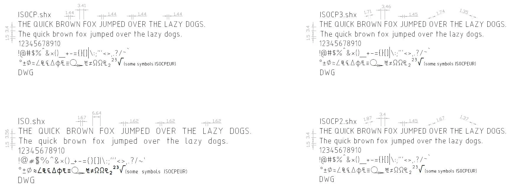
ISOCP shx fonts
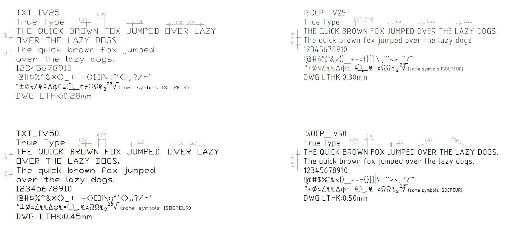
ISOCP with TXT True Type fonts
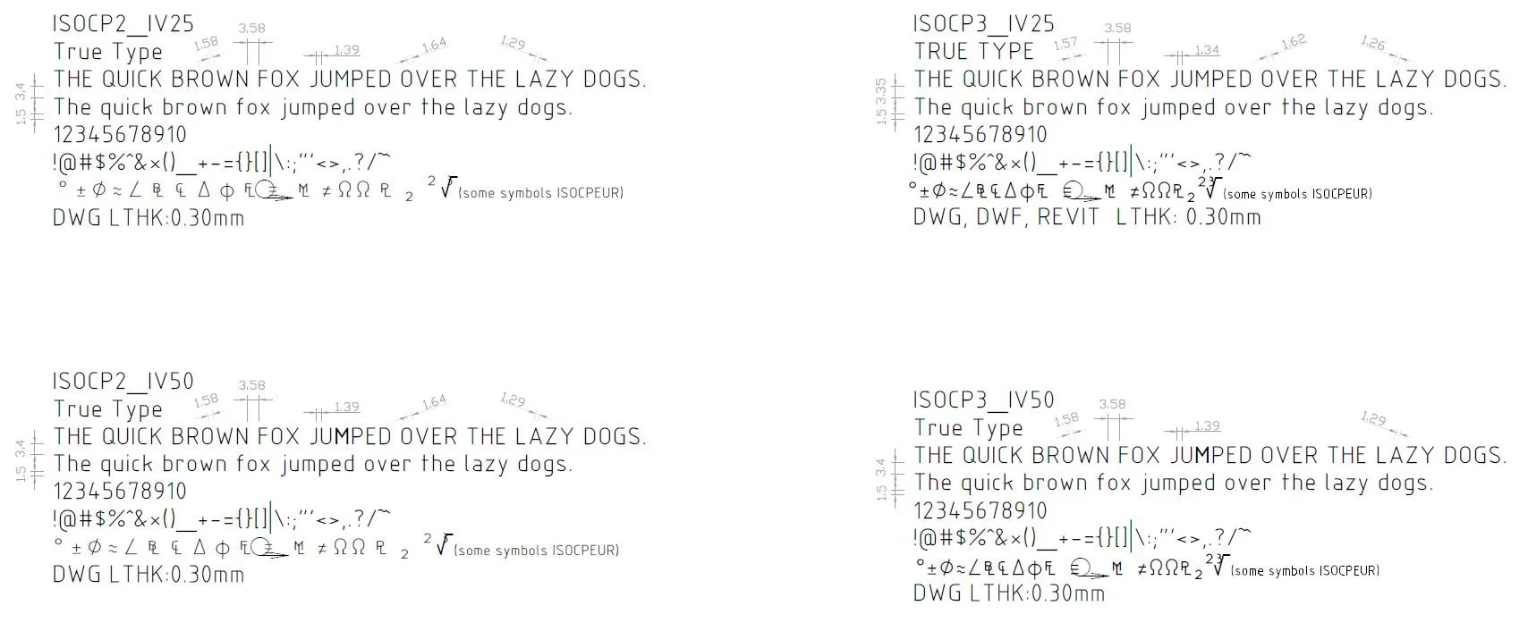
ISOCP True Type fonts
In AutoCAD, I identified the fonts that fit the Gothic criteria. There are several Gothic fonts available, but I opted for MS Gothic fonts and included Century Gothic. Simplex and Roman I also categorized under Gothic. The Microfont type remains a mystery to me.
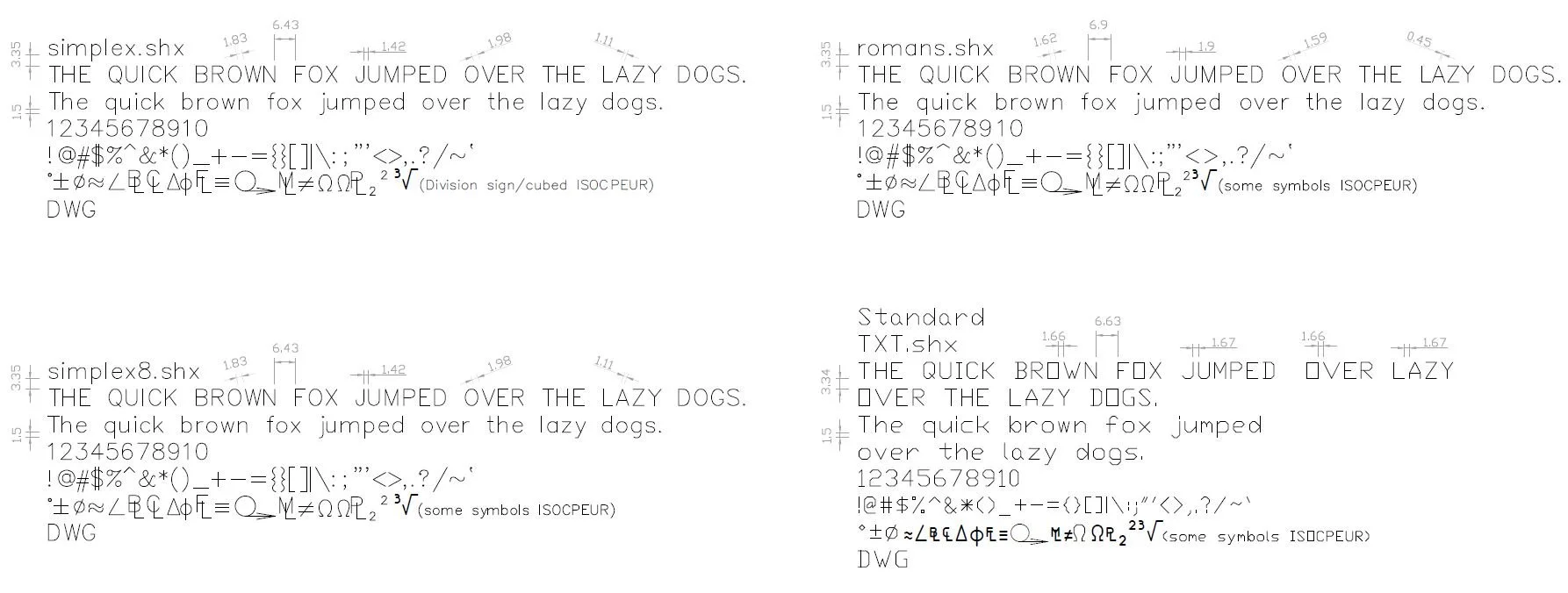
Roman and Simplex shx fonts with a TXT shx font
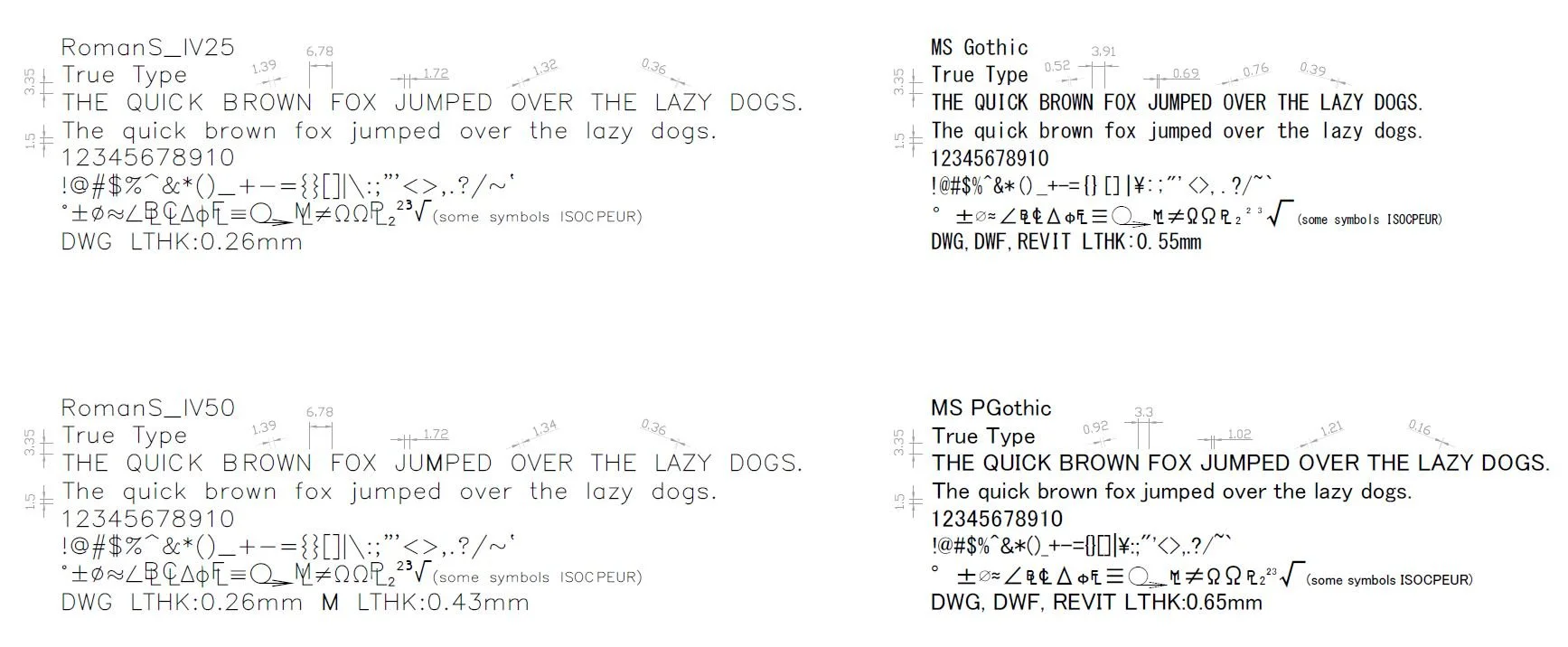
Roman and MS Gothic True Type fonts
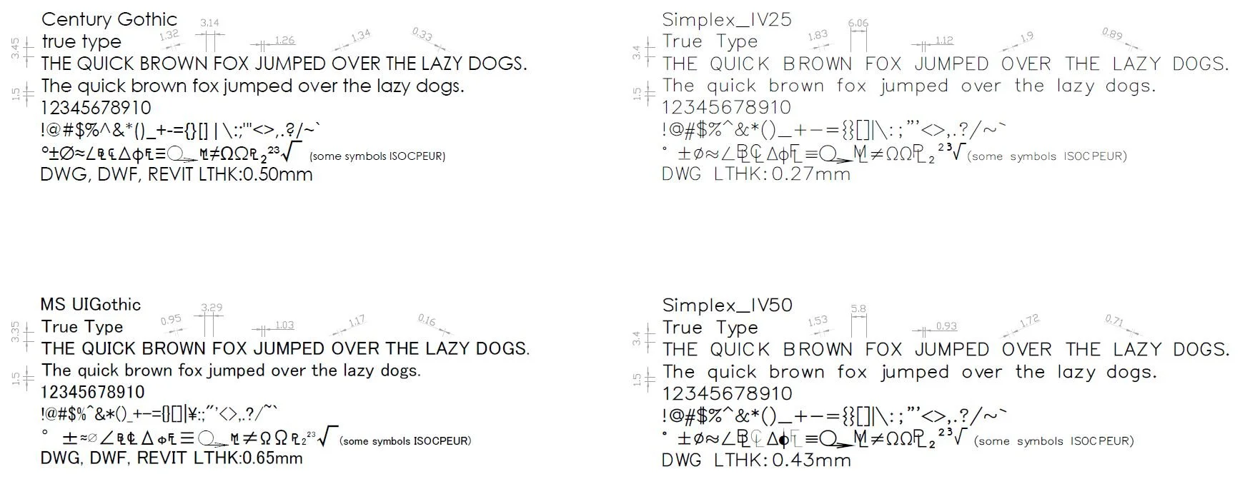
Gothic and Simplex True Type fonts
Other fonts analysed include:
TXT: This appears to be a basic font that is set as the initial standard in the text styles dropdown on the AutoCAD ribbon.
Arial: Previously the default font for all Microsoft Office Software.
Calibri: Replaced Arial as the default font for Microsoft Office in 2007.
Aptos: Introduced in 2024 and replaced Calibri as the default font for Microsoft. However, Aptos was not included in the analysis as it was not available in the AutoCAD fonts selection.

Arial, Calibri and ISOCPEUR True Type fonts
I was unsure about the measurement of the spacing between the letters L and A. Although the characters are in close proximity to each other, considering their appearance, I would adopt a lenient approach in assessing the size between them. The space between the L and the A might not matter much given that they are easily recognizable.
Symbols in fonts that didn't have symbols provided, defaulted to ISOCPEUR.
Certain symbols for ISOCP_IV25, ISOCP_IV50, ISOCP2_IV25, ISOCP2_IV50, ISOCP3_IV25, and ISOCP3_IV50 may not plot correctly, and this issue will not be detected during the preview phase before plotting.
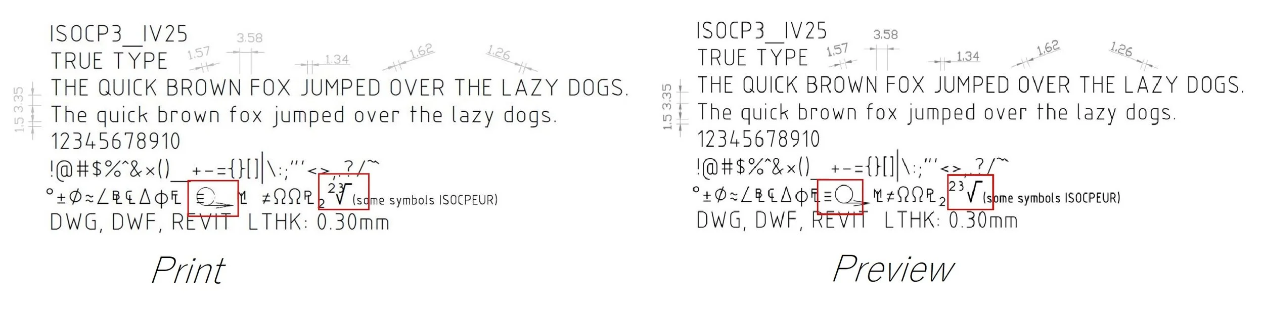
An example of the font when printed and before printing.
I have also outlined the compatibility of fonts from the AutoDESK supported fonts guide. DWG, DWF, and REVIT. This information was obtained from the Autodesk helpdesk. For more details, please refer to the following link: https://help.autodesk.com/view/DOCS/ENU/?guid=Supported_Fonts_Docs
As for my own decision with picking a font, I will go with ISOCPEUR.
What fonts do you use?
Gaye Higgs
Berlin Blue Drafting Services